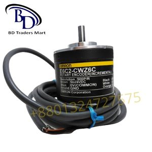
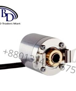
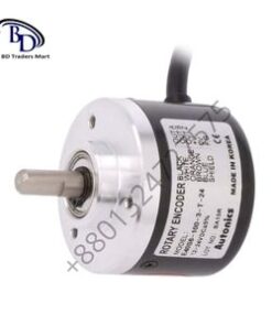
The E6C2-CWZ6C is a common model of incremental rotary encoder manufactured by Omron. It’s designed to measure rotary motion and convert it into electrical signals. Here are some key details about this encoder:
- Voltage Range: The E6C2-CWZ6C encoder operates within a voltage range of 5-24VDC. This means it can be powered using a supply voltage between 5 volts and 24 volts DC.
- Incremental Encoder: This encoder is of the incremental type, which means it produces pulses corresponding to the rotational movement of the shaft. Each pulse represents a certain increment of movement.
- Pulse Output: The encoder generates a series of pulses as the shaft rotates. The number of pulses per revolution (PPR) determines the resolution of the encoder. For instance, if the encoder has 1000 PPR, it will generate 1000 pulses for every full rotation (360 degrees) of the shaft.
- Connection: The E6C2-CWZ6C typically has multiple wires for connection. Common connections include:
- Power Supply (V+): Connect the positive terminal of your power supply (within the 5-24VDC range) to this input.
- Common (COM): This is the ground (negative) terminal of your power supply.
- A Phase Output (A): This wire outputs the A phase pulses of the encoder.
- B Phase Output (B): This wire outputs the B phase pulses, typically used for determining direction of rotation.
- Z Phase Output (Z): This wire outputs an index pulse, usually generated once per revolution.
- Pin Configuration: The pin configuration might vary slightly depending on the specific model, but typically, it follows a standard pinout like:
- Pin 1: Power Supply (V+)
- Pin 2: A Phase Output (A)
- Pin 3: Common (COM)
- Pin 4: B Phase Output (B)
- Pin 5: Z Phase Output (Z)
- Usage: To use the encoder, connect the power supply (5-24VDC) to the appropriate terminals and then use the A and B phase outputs to read the incremental position changes. The Z phase output can be used to detect a reference or home position.
- Interfacing: You can interface this encoder with a microcontroller or PLC (Programmable Logic Controller) to process the pulses and determine the position and direction of rotation. Typically, the A and B phase outputs are connected to interrupt pins or encoder input modules of these devices.
Before connecting and using the encoder, it’s crucial to consult the specific datasheet or manual for the E6C2-CWZ6C model to ensure correct wiring and usage, as there might be slight variations based on the specific variant or model number.


Reviews
There are no reviews yet.